Escrito originalmente por Guest injectorman en 10 de Septiembre del 2008
SCORPIUS ELECTRONICS SPECIFICATIONS
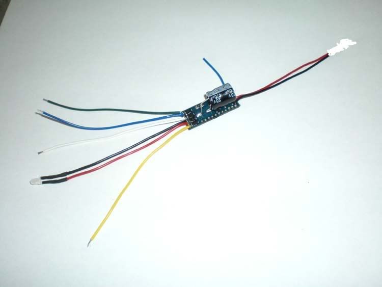
Car Chip
1.1. Electrical
1.1.1 Operates on AC, DC or pulsed DC
1.1.2 8.5 Volts Minimum
1.1.3 18 Volts Maximum
1.1.4 3 Amps Maximum Peak Motor Load Current
1.2. Motor Control
1.2.1 PWM Control Method for Drive and Brake
1.2.2 256 Step Resolution
1.2.3 500 Hz or 4 KHz (default) PWM Frequency
1.2.4 Motor Current detection for Traction Control
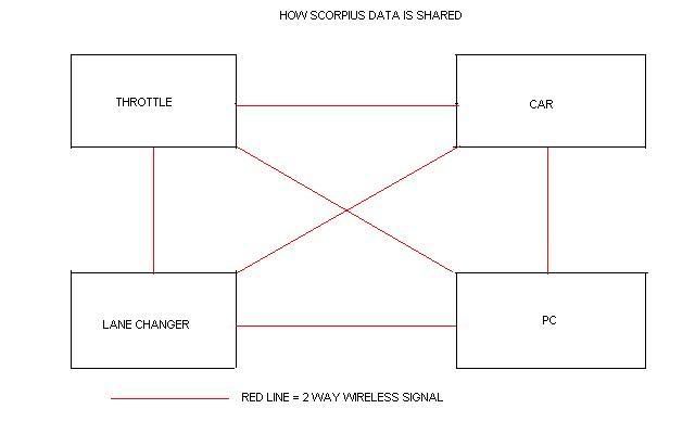
1.3. Wireless Communication
1.3.1 2.4-2.5 GHz ISM band RF transceiver
1.3.2 Receives throttle, lane change, digital output, configuration commands
1.3.3 Transmits lane change requests, status and configuration information
1.3.4 Allows wireless update of chip firmware (re-flashing)
1.4. Electrical Interfaces
1.4.1 IR Photodiode to detect Scorpius lane changer
1.4.2 IR LED for sending car ID and lane change request to SSD System
1.4.3 Data via braid for sending car ID and lane change request to Ninco System
1.4.4 Solenoid Driver for SCX lane change
1.4.5 6 Digital Outputs for lights, horn, etc
1.5. Configuration Information
Note: Configuration information is sent to car using PC Configuration utility and PC RF dongle.
Note: All text fields are limited to 24 characters maximum
1.5.1 Car ID
1.5.2 Car # (physical number on slot-car)
1.5.3 ID Mode, eg: Scorpius, Ninco, SSD, SCX
Note: This setting is not required as all ID modes can operate concurrently
1.5.4 Motor PWM Frequency
1.5.5 Brake settings (%)
1.5.6 Traction control settings (%) Future function
Note; Traction control algorithm to be determined
1.5.7 Fuel Level (%) Or by pclapcounter
1.5.8 Fuel Consumption Rate Or by pclapcounter
Note: Fuel Consumption Algorithm to be determined
1.5.9 Tyre Status (%) Or by pclapcounter
1.5.10 Tyre Wear Rate Or by pclapcounter
Note: Tyre Wear Rate Algorithm to be determined
1.5.11 Driver’s name
1.5.12 Car type
1.5.13 Colour
1.5.14 Livery (eg: Malboro)
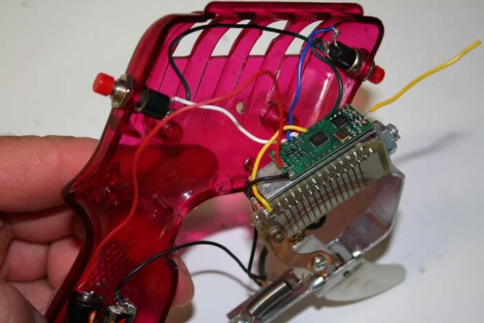
2.1 Throttle Controller
2.1.0 Electrical
2.1.1 Operates on 2 x AAA Alkaline Cells
2.1.2 3 month Battery Life (based on average usage of a few hours per week)
2.1.3 Activates Sleep Mode after 3 minutes of throttle inactivity
Note: In sleep mode the throttle input is checked for activity (throttle input greater than minimum throttle activation level) every 0.5 seconds
2.2. Electrical Interfaces
2.2.1 0 – 5K ohm Throttle Resistance
2.2.2 Lane Change Push Button Switch (N/O or N/C)
2.2.3 Brake Push Button Switch (N/O or N/C)
2.2.4 Inputs for Optional Push Button Switches (N/O or N/C) for Lights, and up to 5 other functions
2.2.5 Electro-mechanical Vibrator
Note: Vibrator is used to alert low fuel and tire wear. It is also used to signal ID and brake level when changed in standalone mode (see below)
2.3. Wireless Communication
2.3.1 2.4-2.5 GHz ISM band RF transceiver
2.3.2 Transmits throttle, lane change requests, digital outputs and basic configuration information
Note: Throttle, lane change and digital outputs are sent to the car 20 times per second
2.3.3 Receives status, and configuration commands
2.3.4 Allows wireless update of throttle firmware (re-flashing)
2.4. Configuration Information
Note: Configuration information is sent to throttle using PC Configuration utility and PC RF dongle.
2.4.1 Throttle ID
2.4.2 Minimum Throttle Activation Level (%)
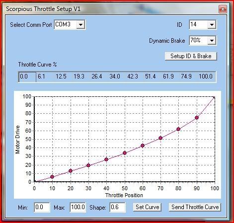
2.4.3 Throttle Curve (10 point table)
2.4.4 Fuel Alert Level (%)
2.4.5 Tyre Wear Alert Level (%)
2.5. Standalone Configuration (without PC Dongle)
2.5.1 Allows Throttle ID to be set
Note: To set throttle ID, wait at least 10 seconds after releasing throttle. Press LC button for 2 seconds. Subsequent short presses of LC button count throttle ID. 2 seconds after last press of LC button, throttle ID is set and is signaled by the vibrator.
2.5.2 Allows Car ID to be set to Throttle ID
Note: To set car ID, wait at least 10 seconds after releasing throttle then remove car from track for at least 5 seconds and replace on track. Press LC button for 2 seconds. 2 seconds after releasing LC button, throttle ID is sent to car and sets car ID.
2.5.3 Allows Brake Level to be set (20% increments)
Note: To set car brake level, car ID must be set to Throttle ID (see above). Wait at least 10 seconds after releasing throttle. Press Brake button for 2 seconds. Subsequent short presses of Brake button increment brake level by 20%. 2 seconds after last press of Brake button, brake level is sent to car.
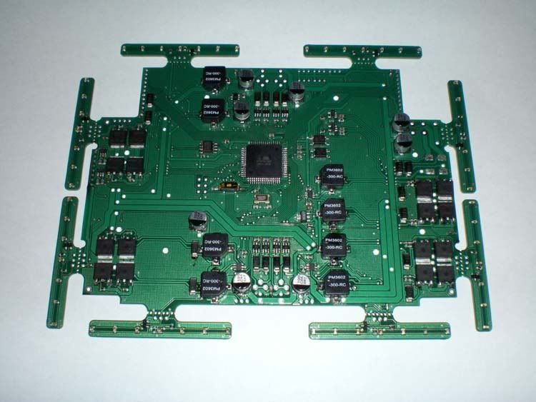
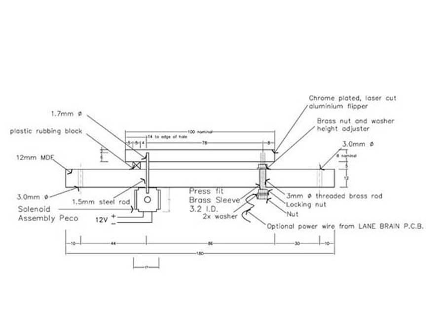
3.1.0 Lane Brain Lane Changer Electronics
Electrical
3.1.1 Operates on DC power
3.1.2 8.0 V min.
3.1.3 13.8 V max
3.1.4 1.5 amp minimum
Wireless Communication
3.1.5 2.4-2.5 GHz ISM band RF transceiver
3.1.6 Receives throttle, lane change, digital output, configuration commands
3.1.7 Transmits lane change requests, status and configuration information
3.1.8 Allows wireless update of chip firmware (re-flashing)
Electrical interfaces
3.1.9 4 x IR LED to transmit LC ID (one on lane 1 & @ entry and Lane 1 & 2 exit for use in bi-directional mode)
3.1.10 2 x 5.0V flipper drivers
3.1.11 4 x spare analogue I/O
3.1.12 4 x spare digital I/O
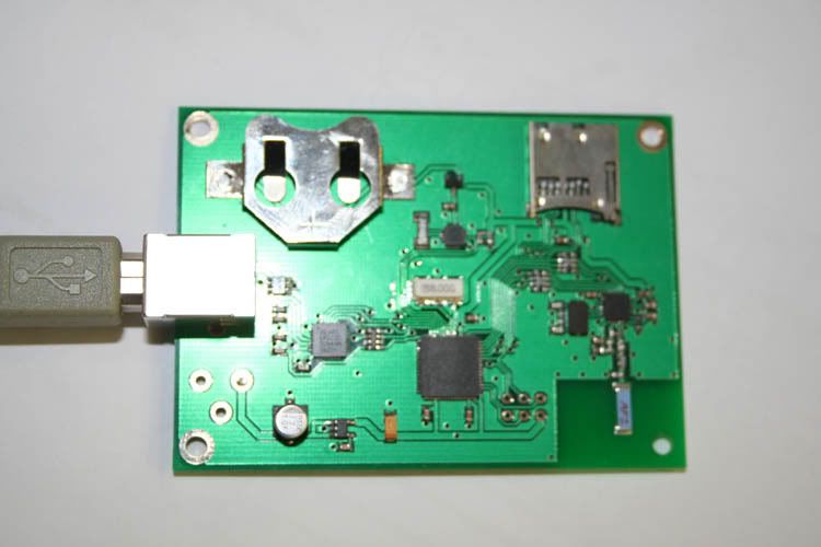
4.1.0 PC RF Dongle
Wireless Communication
4.1.1 2.4-2.5 GHz ISM band RF transceiver, USB powered
4.1.2 Receives throttle, lane change information.
4.1.3 Transmits throttle, car and lane change information.
4.1.4 Allows wireless update of car and throttle ID and parameters.
Rick